友情链接
(400-626-1616转1)
热门友链:
原厂友链:
行业友链:

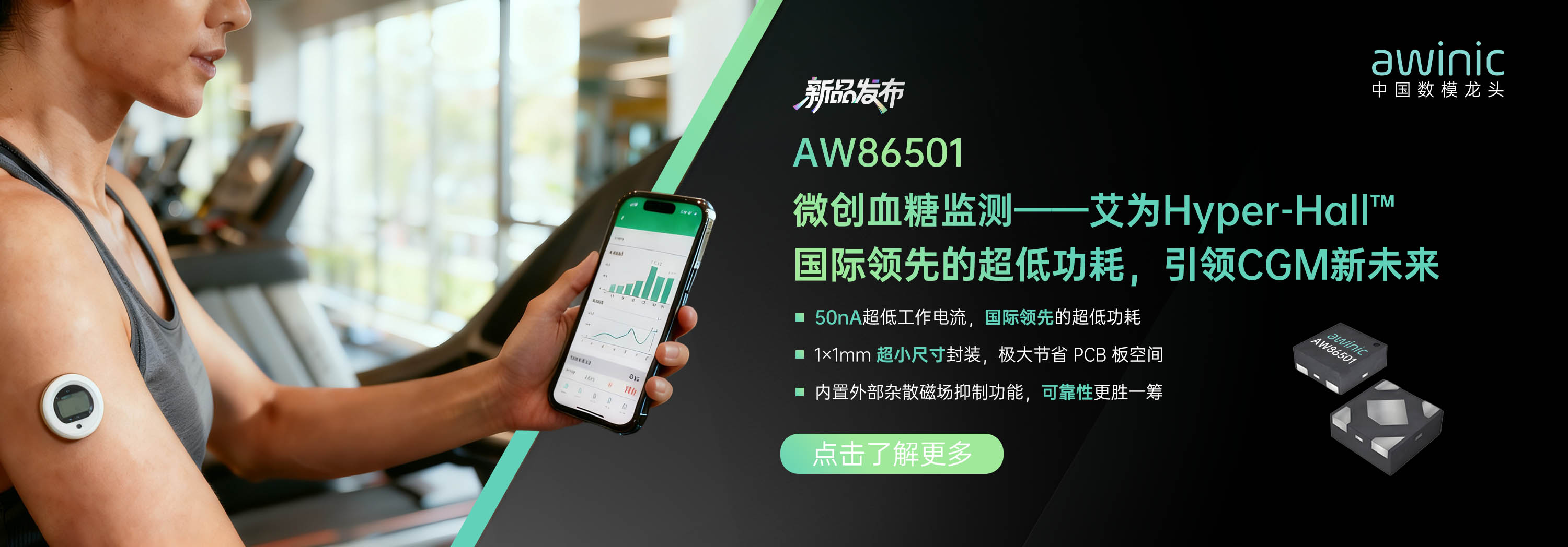
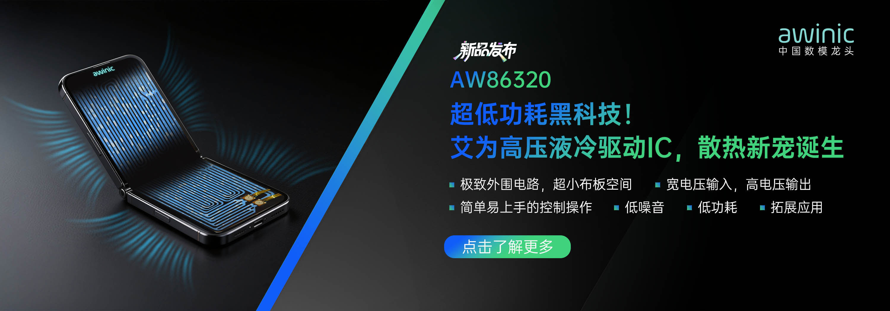
温馨提醒:图片仅供参考,商品以实物为准
 数据手册
数据手册

AW36515 Oct. 2019 V1.1
www.awinic.com.cn 2 Copyright © 2018 SHANGHAI AWINIC TECHNOLOGY CO., LTD
Pin Configuration And Top Mark
GND IN SDA
SW SCL
OUT
LED2 TX LED1D
A
C
B
31 2
V S
D S
X X
X
STROBE/
TORCH
VSDS – AW36515FCR
XXX – Production Tracing Code
AW36515FCR Pin Configuration
(Top View) AW36515FCR Top Mark
(Top View)
Pin Configuration and Top Mark
Pin Definition
No. NAME TYPE DESCRIPTION
A1 GND Ground Ground
A2 IN Power Input voltage connection. Connect IN to GND with a 10µF or larger ceramic capacitor.
A3 SDA I/O Serial data input/output of the I2C interface.
B1 SW Power Switch pin of the step-up DC-DC convertor.
B3 SCL I/O Serial clock input of the I2C interface.
C1 OUT Power Step-up DC-DC converter output. Connect a 10µF ceramic capacitor between OUT and GND.
C3 STROBE/TORCH I/O Active high hardware flash/torch/IR enable. Drive STROBE/TORCH high to turn on Flash/Torch/IR pulse. Internal pull down resistor of 300kΩ between STROBE/TORCH and GND.
D1 LED2 Power High-side current source output for flash LED2.
D2 TX I/O Power amplifier synchronization input. Internal pull down resistor of 300kΩ between TX and GND.
D3 LED1 Power High-side current source output for flash LED1.
Aw in
ic Co
fi en
tia l