之前发过LED点灯测试,这次再来个串口通信的。
硬件、软件、资料等信息,iCEasy官方已经整理的很详细了,我就不做过多介绍了。
https://www.iceasy.com/cloud/RISC-V?pid=1907770165638025220
工程的流程也不再赘述了,注意选对芯片就好: HMQ7
不会新建工程的朋友可以参考我以前发的LED点灯测评中的【新建工程】部分。
https://www.iceasy.com/review/1894699606296567809
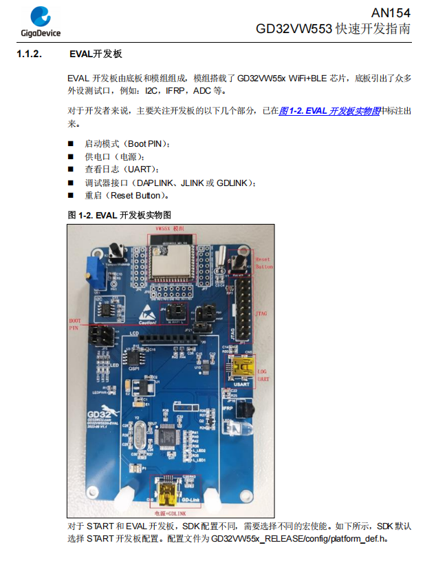
新建好工程之后,IDE默认生成的.c和.h里的内容是与兆易创新官方的EVAL开发板适配的,EVAL开发板有板载的测试LED和测试按键,而我们的iot开发板是没有这些板载资源的,所以,默认生成的.c和.h里面跟EVAL相关的东西使用起来要注意。
新建好工程后,要做以下修改:
1、删除main.h
2、修改main.c:
#include "gd32vw55x.h"
#include "systick.h"
#include <stdio.h>
#include <string.h>
#include "gd32vw553h_eval.h"

#define TX_BUFFER_SIZE  1024
#define RX_BUFFER_SIZE  1024

/* transmit buffer and receive buffer */
uint8_t tx_buffer[TX_BUFFER_SIZE];
uint8_t rx_buffer[RX_BUFFER_SIZE];
/* counter of transmit buffer and receive buffer */
__IO uint16_t tx_count = 0, rx_count = 0;

/* result of the transfer */
__IO ErrStatus transfer_result = ERROR;

void nvic_config(void);

/*!
 \brief      main function
 \param[in]  none
 \param[out] none
 \retval     none
 */
int main(void)
{
	/* USART interrupt configuration */
	eclic_irq_enable(USART0_IRQn, 1, 0);
	systick_config();

	/* initialize the USART */
	gd_eval_com_init(EVAL_COM0);

	//初始发送,跟上位机打个招呼
	strcpy(tx_buffer,
			"Hello Serial. This is GD32VW553-ioT,Please send me some text, and then I'll send it back to you.");

	/* enable USART TBE interrupt */
	usart_interrupt_enable(EVAL_COM0, USART_INT_TBE);

	while (RESET == usart_flag_get(EVAL_COM0, USART_FLAG_TC))
		;

    //循环:等待上位机发送来的数据,每条消息以换行符结束。每收到一条信息,就立马回传给上位机,加上“rx:”方便区分单片机消息。
	while (1)
	{

		/* enable USART RBNE interrupt */
		usart_interrupt_enable(EVAL_COM0, USART_INT_RBNE);
		/* wait until USART receive the rx_buffer */
		while (SET == usart_flag_get(EVAL_COM0, USART_INT_RBNE))
			;
		sprintf(tx_buffer, "rx: %s", rx_buffer);
		/* enable USART TBE interrupt */
		usart_interrupt_enable(EVAL_COM0, USART_INT_TBE);
		while (RESET == usart_flag_get(EVAL_COM0, USART_FLAG_TC))
			;
	}
}3、修改中断头文件gd32vw55x_it.h
#ifndef GD32VW55X_IT_H
#define GD32VW55X_IT_H

#include "gd32vw55x.h"

/* function declarations */
void eclic_mtip_handler(void);
/* this function handles USART2 exception */
void USART0_IRQHandler(void);

#endif /* GD32VW55X_IT_H */
4、修改中断源文件gd32vw55x_it.c
#include "gd32vw55x_it.h"
#include "systick.h"
#include <string.h>
#include "gd32vw553h_eval.h"

extern uint8_t tx_buffer[];
extern uint8_t rx_buffer[];
extern uint32_t rx_buffer_size, tx_buffer_size;
extern uint16_t tx_count, rx_count;

void eclic_mtip_handler(void)
{
	ECLIC_ClearPendingIRQ(CLIC_INT_TMR);
	delay_decrement();
}

/*!
 \brief      this function handles USART RBNE interrupt request and TBE interrupt request
 \param[in]  none
 \param[out] none
 \retval     none
 */
void USART0_IRQHandler(void)
{
	if (RESET != usart_interrupt_flag_get(EVAL_COM0, USART_INT_FLAG_RBNE))
	{
		/* receive data */
		rx_buffer[rx_count] = usart_data_receive(EVAL_COM0);
		if (rx_buffer[rx_count] == '\n')
		{
			usart_interrupt_disable(EVAL_COM0, USART_INT_RBNE);
			rx_count=0;
		}
		else
		{
			rx_count++;
		}
	}

	if (RESET != usart_interrupt_flag_get(EVAL_COM0, USART_INT_FLAG_TBE))
	{
		/* transmit data */
		usart_data_transmit(EVAL_COM0, tx_buffer[tx_count++]);
		if (tx_count >= strlen(tx_buffer))
		{
			usart_interrupt_disable(EVAL_COM0, USART_INT_TBE);
			tx_count=0;
		}
	}
}5、修改gd32vw553h_eval.h
前面说过,这个是IDE默认适配EVAL开发板的,里面定义了一些EVAL板载LED、按键相关的东西,要么我们只留串口com相关的东西,要么我们也在硬件上添加LED和按键。我是只为了测试串口中断,就删掉了LED和按键的东西。
#ifndef GD32VW55X_EVAL_H
#define GD32VW55X_EVAL_H

#ifdef __cplusplus
 extern "C" {
#endif

#include "gd32vw55x.h"

#define COMn                             1U
#define EVAL_COM0                        USART0
#define EVAL_COM0_CLK                    RCU_USART0

#define EVAL_COM0_TX_PIN                 GPIO_PIN_15
#define EVAL_COM0_RX_PIN                 GPIO_PIN_8

#define EVAL_COM0_TX_GPIO_PORT           GPIOB
#define EVAL_COM0_TX_GPIO_CLK            RCU_GPIOB
#define EVAL_COM0_TX_AF                  GPIO_AF_8

#define EVAL_COM0_RX_GPIO_PORT           GPIOA
#define EVAL_COM0_RX_GPIO_CLK            RCU_GPIOA
#define EVAL_COM0_RX_AF                  GPIO_AF_2

/* configure COM port */
void gd_eval_com_init(uint32_t com);


#ifdef __cplusplus
}
#endif

#endif /* GD32VW55X_EVAL_H */6、修改gd32vw553h_eval.c,跟5一样,也要针对我们的iot开发板做一些适配,去掉跟EVAL开发板相关的东西
#include "gd32vw553h_eval.h"

/* private variables */
static rcu_periph_enum COM_CLK[COMn] = {EVAL_COM0_CLK};
static uint32_t COM_TX_PIN[COMn] = {EVAL_COM0_TX_PIN};
static uint32_t COM_RX_PIN[COMn] = {EVAL_COM0_RX_PIN};

/*!
    \brief      configure COM port
    \param[in]  COM: COM on the board
      \arg        EVAL_COM0: COM on the board
    \param[out] none
    \retval     none
*/
void gd_eval_com_init(uint32_t com)
{
    /* enable GPIO clock */
    uint32_t COM_ID = 0U;
    if(EVAL_COM0 == com)
    {
        COM_ID = 0U;
    }

    rcu_periph_clock_enable(EVAL_COM0_TX_GPIO_CLK);
    rcu_periph_clock_enable(EVAL_COM0_RX_GPIO_CLK);

    /* enable USART clock */
    rcu_periph_clock_enable(COM_CLK[COM_ID]);

    /* connect port to USARTx_Tx */
    gpio_af_set(EVAL_COM0_TX_GPIO_PORT, EVAL_COM0_TX_AF, COM_TX_PIN[COM_ID]);

    /* connect port to USARTx_Rx */
    gpio_af_set(EVAL_COM0_RX_GPIO_PORT, EVAL_COM0_RX_AF, COM_RX_PIN[COM_ID]);

    /* configure USART Tx as alternate function push-pull */
    gpio_mode_set(EVAL_COM0_TX_GPIO_PORT, GPIO_MODE_AF, GPIO_PUPD_PULLUP, COM_TX_PIN[COM_ID]);
    gpio_output_options_set(EVAL_COM0_TX_GPIO_PORT, GPIO_OTYPE_PP, GPIO_OSPEED_25MHZ, COM_TX_PIN[COM_ID]);

    /* configure USART Rx as alternate function push-pull */
    gpio_mode_set(EVAL_COM0_RX_GPIO_PORT, GPIO_MODE_AF, GPIO_PUPD_PULLUP, COM_RX_PIN[COM_ID]);
    gpio_output_options_set(EVAL_COM0_RX_GPIO_PORT, GPIO_OTYPE_PP, GPIO_OSPEED_25MHZ, COM_RX_PIN[COM_ID]);

    /* USART configure */
    usart_deinit(com);
    usart_baudrate_set(com, 115200U);
    usart_receive_config(com, USART_RECEIVE_ENABLE);
    usart_transmit_config(com, USART_TRANSMIT_ENABLE);
    usart_enable(com);
}7、systick.h和systick.c无所谓,里面就是延时用的,我们这里没用到,想删就删,想留就留
代码修改完之后,编译生成,烧录,这里也不做赘述了
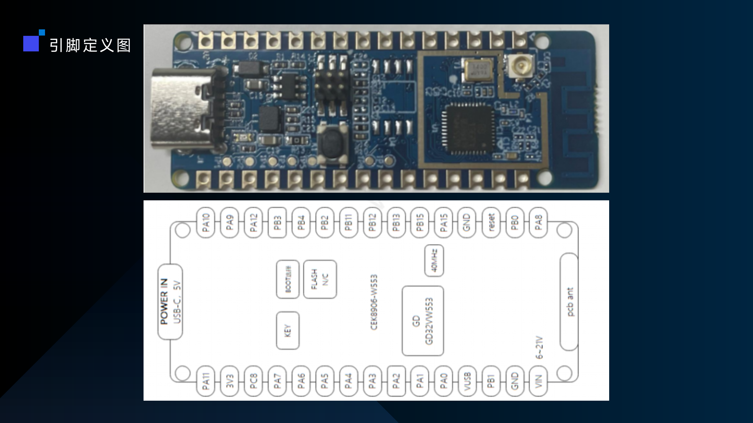
烧录完成后,boot跳线设置好,串口ttl连接电脑,注意我们代码里用的是iot的com0,所以:
ttl_tx——》iot的PA8(UART0.rx)
ttl_rx——》iot的PB15(UART0.tx)
连好GND和供电,电脑端打开常用的串口调试工具,打开串口,iot复位,电脑端串口调试工具会先收到iot发来的打招呼信息,之后,上位机无论发什么内容,iot都会将消息回传给电脑端串口调试工具
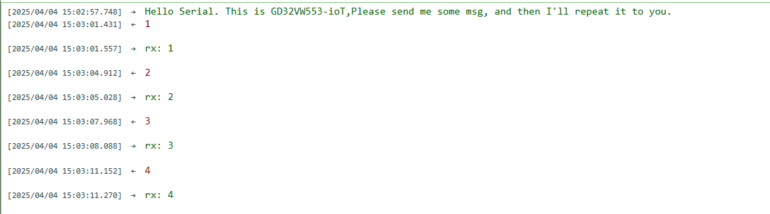
上位机串口调试工具窗口视频效果:
【萤火工场GD32VW553-IOT开发板 中断模式串口收发通信】
https://www.bilibili.com/video/BV1HuZoYjEqx/?share_source=copy_web&vd_source=2a3cb18c475b8e2d2601f09cd41a561e