
 开源社区
开源社区
我使用的是官方的GD32EmbeddedBuilder,链接是:
https://www.gd32mcu.com/data/documents/toolSoftware/GD32EmbeddedBuilder_v1.5.2.30854.7z
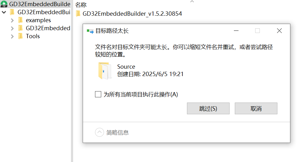
如果遇到类似目标路径太长的问题,可选择放在本身较短的路径下,也可以参考 https://learn.microsoft.com/zh-cn/windows/win32/fileio/maximum-file-path-limitation?tabs=registry#enable-long-paths-in-windows-10-version-1607-and-later 在管理员权限下使用Powershell运行
New-ItemProperty -Path "HKLM:\SYSTEM\CurrentControlSet\Control\FileSystem" -Name "LongPathsEnabled" -Value 1 -PropertyType DWORD -Force首先新建项目,主要要选Project,在下一步再选C Project
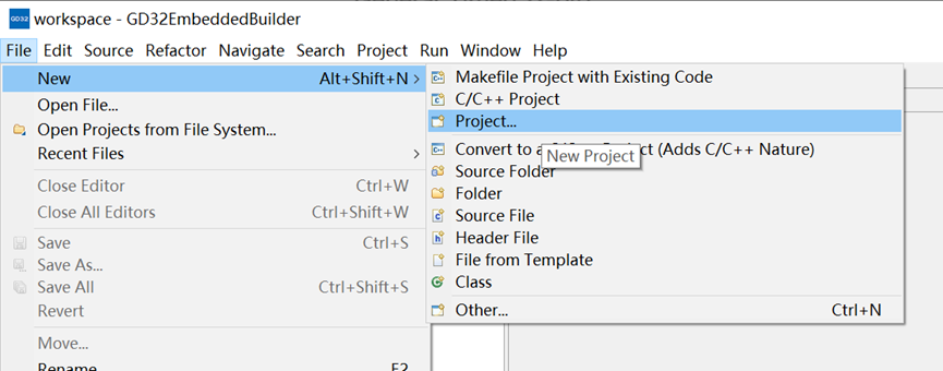
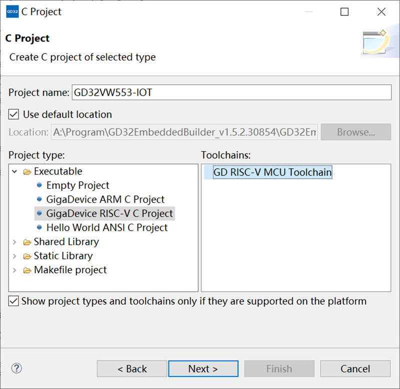
选择 C Project
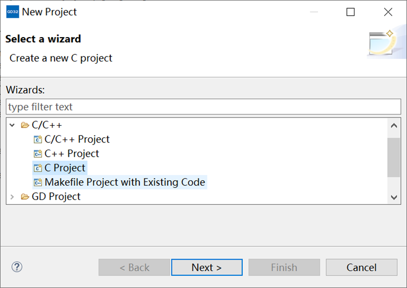
选择Executable,然后选择GigaDevice RISC-V Project,然后选择GD RISC-V MCU Toolchain
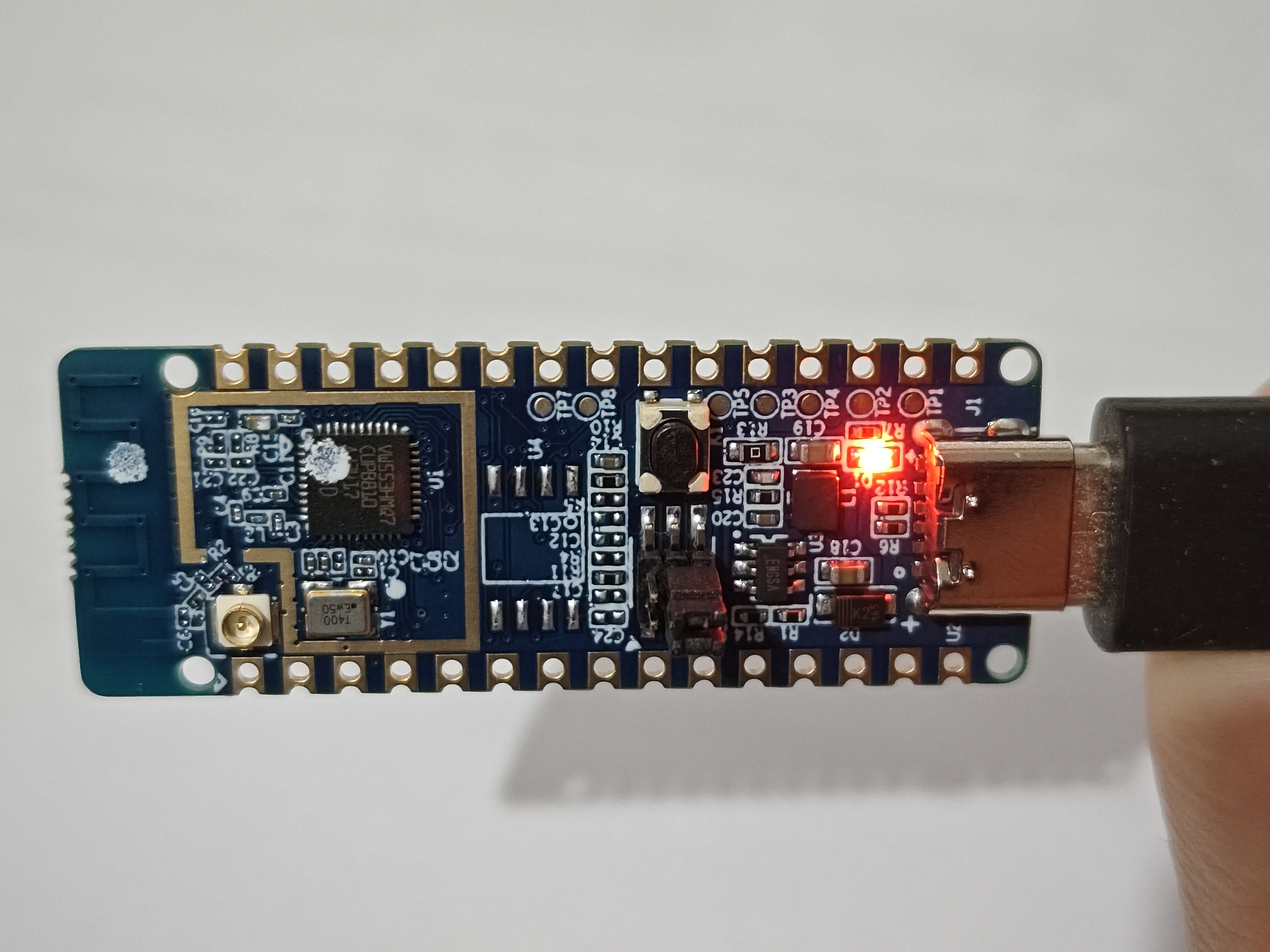
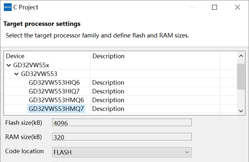
根据iCEasy商城中的性能参数
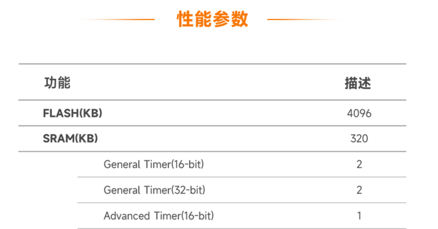
选择GD32VW553HMQ7
此时项目就初始化完毕了,当前项目文件夹内会是一个官方准备好的Template,很方便。
尝试一个输出三路不同占空比的PWM
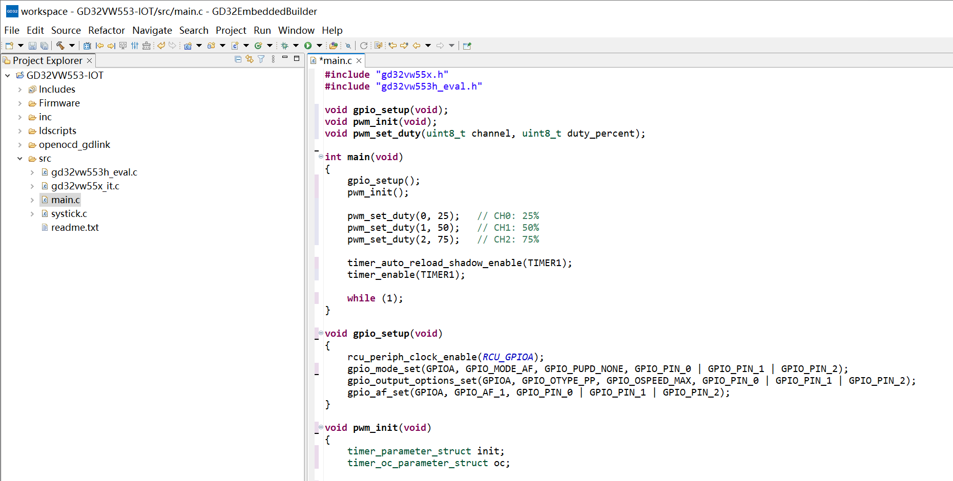
#include "gd32vw55x.h"
#include "gd32vw553h_eval.h"

void gpio_setup(void);
void pwm_init(void);
void pwm_set_duty(uint8_t channel, uint8_t duty_percent);

int main(void)
{
    gpio_setup();
    pwm_init();

    pwm_set_duty(0, 25);   // CH0: 25%
    pwm_set_duty(1, 50);   // CH1: 50%
    pwm_set_duty(2, 75);   // CH2: 75%

    timer_auto_reload_shadow_enable(TIMER1);
    timer_enable(TIMER1);

    while (1);
}

void gpio_setup(void)
{
    rcu_periph_clock_enable(RCU_GPIOA);
    gpio_mode_set(GPIOA, GPIO_MODE_AF, GPIO_PUPD_NONE, GPIO_PIN_0 | GPIO_PIN_1 | GPIO_PIN_2);
    gpio_output_options_set(GPIOA, GPIO_OTYPE_PP, GPIO_OSPEED_MAX, GPIO_PIN_0 | GPIO_PIN_1 | GPIO_PIN_2);
    gpio_af_set(GPIOA, GPIO_AF_1, GPIO_PIN_0 | GPIO_PIN_1 | GPIO_PIN_2);
}

void pwm_init(void)
{
    timer_parameter_struct init;
    timer_oc_parameter_struct oc;

    rcu_timer_clock_prescaler_config(RCU_TIMER_PSC_MUL4);
    rcu_periph_clock_enable(RCU_TIMER1);

    timer_deinit(TIMER1);

    init.prescaler         = 159;
    init.alignedmode       = TIMER_COUNTER_EDGE;
    init.counterdirection  = TIMER_COUNTER_UP;
    init.period            = 15999;
    init.clockdivision     = TIMER_CKDIV_DIV1;
    init.repetitioncounter = 0;
    timer_init(TIMER1, &init);

    oc.outputstate  = TIMER_CCX_ENABLE;
    oc.outputnstate = TIMER_CCXN_DISABLE;
    oc.ocpolarity   = TIMER_OC_POLARITY_HIGH;
    oc.ocnpolarity  = TIMER_OCN_POLARITY_HIGH;
    oc.ocidlestate  = TIMER_OC_IDLE_STATE_LOW;
    oc.ocnidlestate = TIMER_OCN_IDLE_STATE_LOW;

    timer_channel_output_config(TIMER1, TIMER_CH_0, &oc);
    timer_channel_output_config(TIMER1, TIMER_CH_1, &oc);
    timer_channel_output_config(TIMER1, TIMER_CH_2, &oc);

    timer_channel_output_mode_config(TIMER1, TIMER_CH_0, TIMER_OC_MODE_PWM0);
    timer_channel_output_mode_config(TIMER1, TIMER_CH_1, TIMER_OC_MODE_PWM0);
    timer_channel_output_mode_config(TIMER1, TIMER_CH_2, TIMER_OC_MODE_PWM0);

    timer_channel_output_shadow_config(TIMER1, TIMER_CH_0, TIMER_OC_SHADOW_DISABLE);
    timer_channel_output_shadow_config(TIMER1, TIMER_CH_1, TIMER_OC_SHADOW_DISABLE);
    timer_channel_output_shadow_config(TIMER1, TIMER_CH_2, TIMER_OC_SHADOW_DISABLE);
}

void pwm_set_duty(uint8_t channel, uint8_t duty_percent)
{
    uint32_t pulse = (duty_percent * 16000UL) / 100;

    switch (channel) {
        case 0:
            timer_channel_output_pulse_value_config(TIMER1, TIMER_CH_0, pulse);
            break;
        case 1:
            timer_channel_output_pulse_value_config(TIMER1, TIMER_CH_1, pulse);
            break;
        case 2:
            timer_channel_output_pulse_value_config(TIMER1, TIMER_CH_2, pulse);
            break;
        default:
            break;
    }
}
这款和以往的GD32的区别除了采用RISC-V架构外,我觉得影响最大的是集成了WiFi和BLE,这部分感觉目前网上资料还比较少,开发的话可以参考以下网址:
https://gd32mcu.com/data/documents/applicationNote/AN158_GD32VW553_Wi_Fi_kaifazhinan.pdf
其它例程:
https://www.gd32mcu.com/data/documents/toolSoftware/GD32VW55x_Firmware_Library_V1.4.0.7z